


Prio Cooling Water Scale Inhibitor: Planning Feed Points and Mixing
Scale on a heat exchanger can persist even when the dosing pump appears to be running normally. One possible cause is poor distribution: the inhibitor enters a quiet basin corner, passes directly toward blowdown, or reaches only part of the circulating flow. For Prio Cooling Water Scale Inhibitor, the practical starting point is a feed location with reliable circulation, enough mixing before scale-prone equipment, and separation from concentrated incompatible chemicals.
Do not select a connection simply because it is close to the chemical tank. Trace the water path under normal and reduced-load operation, confirm the actual chemical delivery rate, and identify where representative samples can be taken. These checks help distinguish a distribution problem from an unsuitable treatment dose or changing water chemistry.
Trace the water route before choosing the connection
Mark the cooling tower basin, circulating pumps, supply header, heat exchangers, return header, makeup entry, and blowdown connection on a simple flow sketch. Add existing acid, oxidizing biocide, corrosion inhibitor, and dispersant injection points. The important question is whether the proposed point carries the inhibitor into the water serving every protected branch.
Pay particular attention to standby pumps, bypasses, isolated cells, and seasonal operating arrangements. A header that mixes well at full flow may provide weak distribution when only one pump operates. Likewise, a basin compartment can remain poorly exchanged even while the overall system circulation is high.
- Confirm continuous flow: exclude dead legs and connections that become stagnant during routine operation.
- Check the route to vulnerable surfaces: allow mixing before the first exchanger, rather than injecting immediately at its inlet without verification.
- Locate potential losses: avoid feed positions where concentrated treatment can leave directly through blowdown or overflow.
- Identify separate circuits: hydraulically isolated loops may need individual feed and monitoring arrangements.
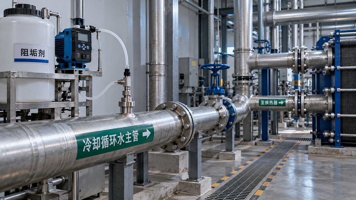
Compare practical feed locations
A point upstream of a circulating pump can provide useful mixing, but it is not automatically the best choice. Confirm pump and seal compatibility, inlet hydraulics, and the consequences of concentrated chemical contact. Never modify a pump suction connection without an equipment review.
For pressurized pipe injection, use a suitably rated injection assembly that introduces chemical into moving water rather than leaving it against the pipe wall. Quill position, orientation, materials, and insertion length require piping-specific selection. There is no universal straight-pipe distance that proves complete mixing; flow velocity, pipe geometry, branches, and injection design all matter.
Keep concentrated chemical streams apart
Compatibility in circulating water does not establish compatibility between concentrated products. Separate inhibitor injection from acid, hypochlorite, and other treatment feeds so that each chemical is dispersed before the streams interact. Do not share a day tank, suction manifold, or injection fitting unless compatibility has been explicitly confirmed.
Where a treatment formulation uses 2-Phosphonobutane -1,2,4-Tricarboxylic Acid, Sodium salt (PBTCA·Na4), its scale-inhibiting properties, zinc-salt stabilization, and chlorine oxidation resistance can be relevant to cooling water treatment. These properties do not remove the need for separate concentrated feeds or establish compatibility with every biocide or corrosion inhibitor.
Confirm whether the supplied material is a raw ingredient or a finished blend before setting the pump. Product concentration, density, and the basis used to report active content affect the conversion between a treatment recommendation and a volumetric feed rate. A raw-material specification is not an operating dose for the complete cooling system.
Dilution also needs approval. Check the permitted dilution ratio, dilution-water quality, storage time, and wetted-material compatibility against the product documentation. Hard dilution water or contamination from previously used containers can introduce instability before the chemical reaches the injection point.
Make the dosing equipment match the operating conditions
A running pump does not prove chemical delivery. Gas locking, worn valves, a blocked injection fitting, or insufficient discharge pressure can reduce output while the controller still indicates operation. Calibrate delivery using the installed arrangement and representative backpressure, following the equipment procedure.
- Verify the hydraulic duty. Check the highest expected line pressure, suction conditions, and pump capacity across the required operating range.
- Provide appropriate protection. Select non-return, anti-siphon, pressure-relief, and backpressure provisions according to the installation. Keep isolation and maintenance access practical.
- Link feed to actual circulation. A proven-flow interlock is more dependable than a pump-run signal alone. Prevent chemical accumulation in a stopped line.
- Choose a suitable control basis. Makeup-proportional dosing may suit stable conditions, but variable losses, inventory changes, or product demand can require additional feedback.
Do not calculate continuous replacement feed from recirculating flow alone. Water repeatedly passing through the loop is not repeatedly lost. Maintenance dosing normally considers makeup, blowdown, drift, leakage, and any treatment-specific depletion; establishing the initial system inventory is a separate calculation. Use the approved treatment program to set both.
Verify mixing under real operating conditions
Commission the arrangement at the operating states most likely to expose weak distribution: minimum circulation, different pump combinations, and normal blowdown operation. Record the chemical feed rate, water flows where available, conductivity, pH, and sampling locations so that comparisons have context.
Use an approved product assay or compatible tracer method to compare representative points after sufficient circulation time. Suitable locations may include the main supply header, a distant branch, and the return. A sample immediately beside the injector can overstate treatment availability elsewhere. Flush sampling lines and keep collection procedures consistent.
Conductivity alone does not confirm inhibitor distribution. It mainly reflects dissolved ionic content and can change with makeup and blowdown. Likewise, total phosphorus may include contributions from other treatment chemicals or source water; it should not automatically be interpreted as the active inhibitor residual.
Persistent differences between branches suggest a hydraulic or sampling issue worth investigating before raising the dose. Check valve positions, bypass flow, sample-line stagnation, and the injection route. If mixing remains inadequate, relocating the feed, improving the injection assembly, or evaluating an engineered mixer may be more appropriate than adding chemical.
Use operating symptoms to decide the next adjustment
Deposits near the injector warrant inspection for local precipitation, concentrated chemical interaction, or poor entry into the stream. Fouling confined to one exchanger instead points toward branch flow, wall temperature, or local water conditions. Increasing the system-wide dose without checking these differences can obscure the cause.
When residuals fluctuate throughout the loop, compare pump calibration, tank consumption, makeup changes, and blowdown records. Stable distribution with continuing scale calls for a review of saturation conditions, cycles of concentration, heat-transfer surface temperatures, and formulation suitability—not repeated feed-point changes.
Before opening an injection assembly, isolate, depressurize, and follow site chemical-handling and lockout procedures. Recheck distribution after pump changes, tower-cell isolation, piping modifications, or revised chemical programs; each can invalidate an arrangement that previously mixed adequately.

ONLINE CONSULTATION
If you have any questions, please contact us and we will contact you as soon as possible.